PUBLIC RELEASE: GRIME AI Software for Ground-Based Time-Lapse Imagery

The project folder on my computer is labeled “2021_GRIME_AI.” The date is a reminder of time and energy invested in GRIME AI. Our motivation has always been to enable others to extract information from imagery and we’re thrilled to share this software that facilitates the entire data science workflow, from data acquisition to visualization/exploration to model building and deployment.

John Stranzl is the lead developer of GRIME AI. Including the prototype he brought to the GRIME Lab, he has written almost every line of code. He had the vision to create the complete data science workflow, from data acquisition to model deployment, in GRIME AI.

Special credit goes to Mary Harner at University of Nebraska at Kearney. Mary’s connection with the Platte Basin Timelapse project and depth of experience with image-based projects for science and communication were foundational for GRIME AI. Her mentorship skills are unparalleled and a benefit to many students who have participated in GRIME Lab projects.

Ken Chapman, who developed the first GRIME software (GRIME2) and conducted the prototype study for GRIME AI workflow, deserves all kinds of credit as well. Without Ken’s relentless energy, expertise, and networking skills, we would never have connected with John or built GRIME AI.

This is the first public release of GRIME AI. As early testers, we’ve encountered a few “undocumented features”—but our beta testing experience confirms that the benefits GRIME AI delivers far outweigh any reason to delay its debut. This marks the beginning of something much bigger, and we’re thrilled to finally share GRIME AI with the world.

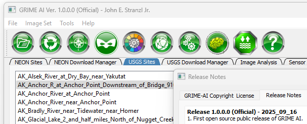
Download the installer: Go.unl.edu/GRIMEAIUserForm

Visit the GRIME AI Wiki: Github.com/JohnStranzl/GRIME-AI/wiki

GitHub Repository: Github.com/JohnStranzl/GRIME-AI

We have been fortunate to have support, financial and moral, from like-minded individuals and agencies. Thank you to Frank Engel, Keegan Johnson, Russ Lotspeich for the opportunity to work with USGS. Thank you to Marty Briggs for connecting us. And to the National Science Foundation for funding and collaborator Andrew Richardson (NAU/PhenoCam) for joining us on this journey. We are truly “living the dream” when we can match exciting projects with great collaborators and humans.

U.S. Geological Survey Logo
This material is based upon work supported by the U.S. Geological Survey under Grant/Cooperative Agreement No. G23AC00141-00. The views and conclusions contained in this document are those of the authors and should not be interpreted as representing the opinions or policies of the U.S. Geological Survey. Mention of trade names or commercial products does not constitute their endorsement by the U.S. Geological Survey.
NSF Logo
This material is based upon work supported by the National Science Foundation under Grant No. 2411065.

GRIME-AI: A Quick Check on Time Required for Accessing and Processing USGS HIVIS Imagery

This video shows steps and time required for data download and image analysis of over 5,000 images from a USGS HIVIS site on the Elkhorn River in Nebraska. The process includes setting regions of interest (ROIs) and extraction of color and other scalar image features suitable for machine learning applications. This work was done on a laptop computer running GRIME-AI v0.0.3.8c-003.

PROCESSES COMPLETED:

• Data selection

• Imagery download

• Stage and discharge data download

• Image processing

• Image feature dataset created

• Ready for data fusion, then ML modeling

LAPTOP SPECIFICATIONS:

Intel i7-9850H @ 2.60GHz 2.59GHz

32 GB RAM

NVIDIA GeForce GTX 1650

Home fiber internet connection over Wifi

TIME REQUIRED:

The overall process took 1:04 hours, including all download and processing time. Extrapolating, this suggests about 4:15 hours required to download and process one year’s worth of imagery when working in my home office.

GRIME-AI Open-Source Software for Analysis of Ground-based TIme-lapse Imagery for Ecohydrological Science

What does it take to install GaugeCam? Here are the gritty details and caveats.

Today I wrote a long email to a colleague interested in setting up GaugeCam. Why not share (a lightly-edited version) with the world?!

First, here’s a recent animation of me installing a target. This might take a moment to load.

animation of image-based water level camera installation
Installation of stop-sign target for GaugeCam water level measurement system.

Second, there are a number of additional resources available at https://gaugecam.org/grime2-details/, including this document that describes the installation details for a bowtie target at our North Carolina tidal marsh site: http://gaugecam.org/wp-content/uploads/2022/06/Gaugecam_org_background_installation_guideline.pdf.

A small photo gallery of a stop-sign target installation in Nebraska:

Some practical considerations and details:

  1. The first question that needs to be answered is the level of reliability and accuracy that is required for your application. If this is an easily-accessed (for maintenance) “demo” site, then this system is perfect for facilitating science communication, etc. If it’s a remote site, with only occasional access for maintenance and data collection, we strongly recommend putting in a cheap transducer alongside the GaugeCam system (e.g., HOBO, $300).
  2. Accuracy depends on (1) how many real-world mm or cm are represented by each pixel in the image, and (2) the quality of installation and maintenance of the background target. The following are issues to consider for field application:
    1. In controlled lab experiments, we can achieve high accuracy (+/- 3 mm, about the size of a meniscus; see Gilmore et al. 2013).
    2. In a carefully maintained tidal marsh installation, accuracy was less, but still quite good (see Birgand et al. 2022).
    3. You will encounter foggy mornings, spider webs on lens, and other similar environmental issues when using cameras. Expect data gaps of minutes to hours due to these issues.
    4. While biofouling is a universal problem for many reasons for many applications and industries, we are actively working to mitigate biofouling affects in our application. In the nutrient-rich agricultural streams where we work, biofouling accumulates within 7-10 days, which requires regular cleaning.
    5. The background must be plumb (perpendicular to the water surface).
    6. The original bow-tie target (template here, nominally 3’ x 4’) was used in the studies above. The new stop-sign target (template here, nominally 2’ x 4’) is experimental, but is smaller and still seems to give pretty good results. The bow-tie requires a survey of the real-world location of bowtie intersections. The stop-sign target requires only the facet length measurement (assumed to be the same for all 8 facets on the printed target) and reference measurement from the bottom left corner.
  3. In terms of installation, here is a parts list from my recent installations in sandy to slightly gravelly streambeds:
    1. Target
      1. Target background, matte print laminated on plexiglass*
      2. Two treated 4×4 posts, 8’ long [NOTE: before digging post holes you should have utilities located; contact your local utilities for this (usually free) service!]
      3. Two treated 2×4 boards, 8’ long
      4. Two Post- Base Spike for 4×4 Nominal Lumber**
      5. One ¾” treated sheet of plywood***
      6. Short (1” or 1 ¼”) pan-head screws (for attaching the plexiglass to the plywood)
      7. Long (3”) outdoor decking screws
      8. Thin wood wedges or spacers (for adjusting background so it is plumb – you might be able to cut these in the field)
    2. Camera
      1. We suggest Reconyx cameras due to their quality, though nearly any game camera will do
      2. Suggest RAM mount products to minimize any camera movement (example 1, example 2)
      3. Suggest adding a lock on camera for security
      4. Suggest treated 4×6 post for mounting the camera; 4×4 post as very minimum.
      5. Camera can be mounted on a large tree or similar, but this will usually create a good bit of movement of the camera. Small amounts of movement can be handled by the software, but minimal movement is better.
    3. Tools that you need (at the very minimum)
      1. Sledge hammer
      2. Post hole digger
      3. Cordless drill
      4. Cordless saw(s) (at least a reciprocating saw)
      5. Level
      6. Measuring tape
      7. Screwdriver

*We are looking for a better alternative that does not require as much cleaning and/or is more resistant to biofouling. The matte finish seems like a good attachment surface for biofouling. If you find a local sign shop for printing, I can send you the contact info for my sign shop so they can talk.

**I have used these in the sandy streams, where I cannot dig holes more than ~1 ft into the streambed (the sand collapses in), so adding these spikes on the bottom helps solidify the installation.

***You can print the background on very thick plexiglass and skip the plywood, but I found this to be expensive. So I printed on ¼” plexiglass and mounted on plywood backing.