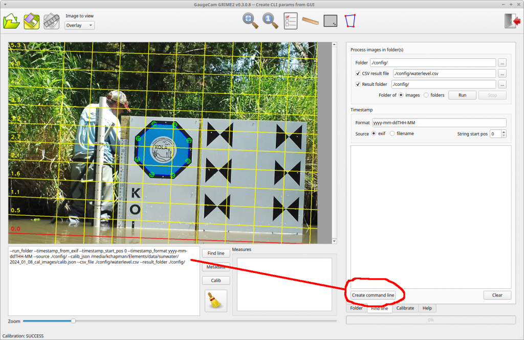
This release makes the creation of CLI calls much easier. The ROI’s and other parameters you select in the GUI can be used to create CLI parameters and output them as test to the textbox below the main image. There are two “Create command line” buttons: one on the Calibration tab and one on the Find Line tab.
This post describes the first testing of a mini-octagon calibration target for measuring water level with a camera and machine vision algorithms.
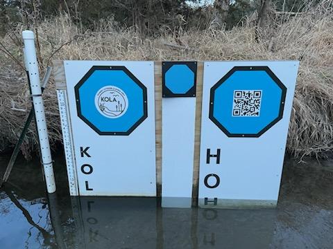
Mini-octagon (center) is approximately eight inches across, leading to a much smaller footprint for the target background. The other two octagons in the image are printed on plexiglass backgrounds two feet in width. Image credit: Mary Harner
The original GaugeCam “bow-tie” calibration target was about three feet wide and four feet tall. This target yielded excellent calibration and precise water level readings. However, the size of the target is obtrusive in images and prohibitive at some sites.
The next generation calibration target, the “octagon target,” is approximately two feet wide. The benefits of the octagon are that (1) the target footprint is much smaller, and (2) the calibration target remains above the water line, so a calibration can be performed for every image. Calibrating each image is more robust because it accounts for camera movement, which is inevitable. The large octagon target performs on par with the original bow-tie calibration target, as shown in Ken Chapman’s dissertation.
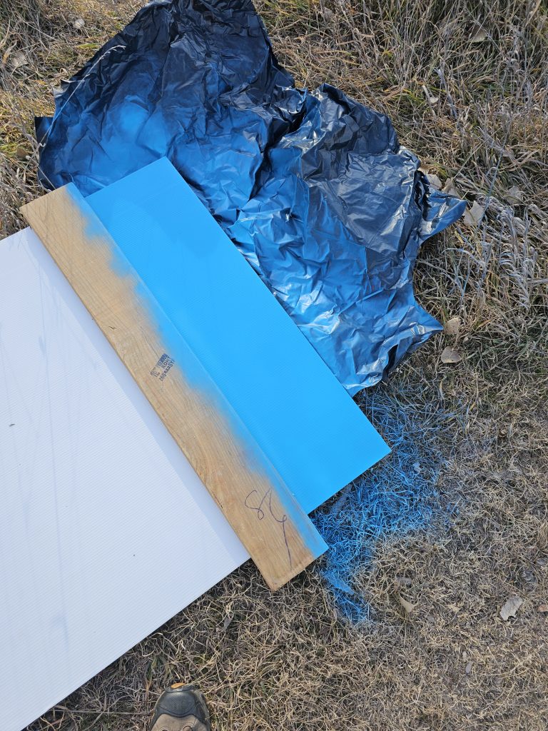
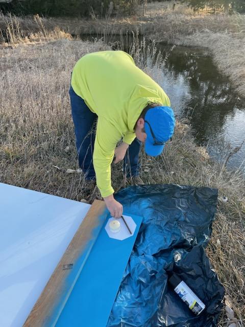
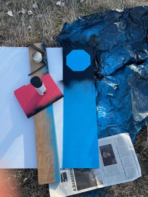
Our goal with the mini-octagon is to reduce the target background to the minimal size required for robust calibration and water level measurement. The current size is larger than a traditional staff gauge but reasonable size for installation in many environments. Below you can see our field fabrication of the first mini-octagon, using a sheet of Coroplast, spray paint, and octagon stencil.
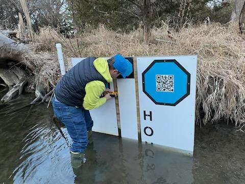
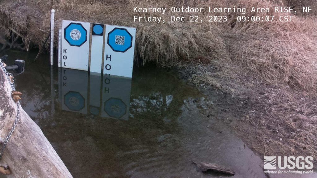
Test installation of the mini-octagon target at Kearney Outdoor Learning Area (KOLA). Photo Credit: Mary Harner
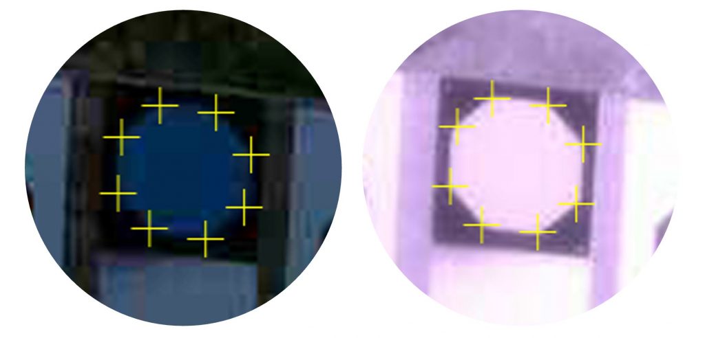
Initial tests show that our algorithms can detect the vertices of the mini-octagon in low-light conditions and under IR illumination.
Mini-octagon detection for image calibration. We are working to determine how much calibration precision is reduced by the smaller octagon.The latest KOLA imagery can be found at https://apps.usgs.gov/hivis/camera/NE_Kearney_Outdoor_Learning_Area_RISE.
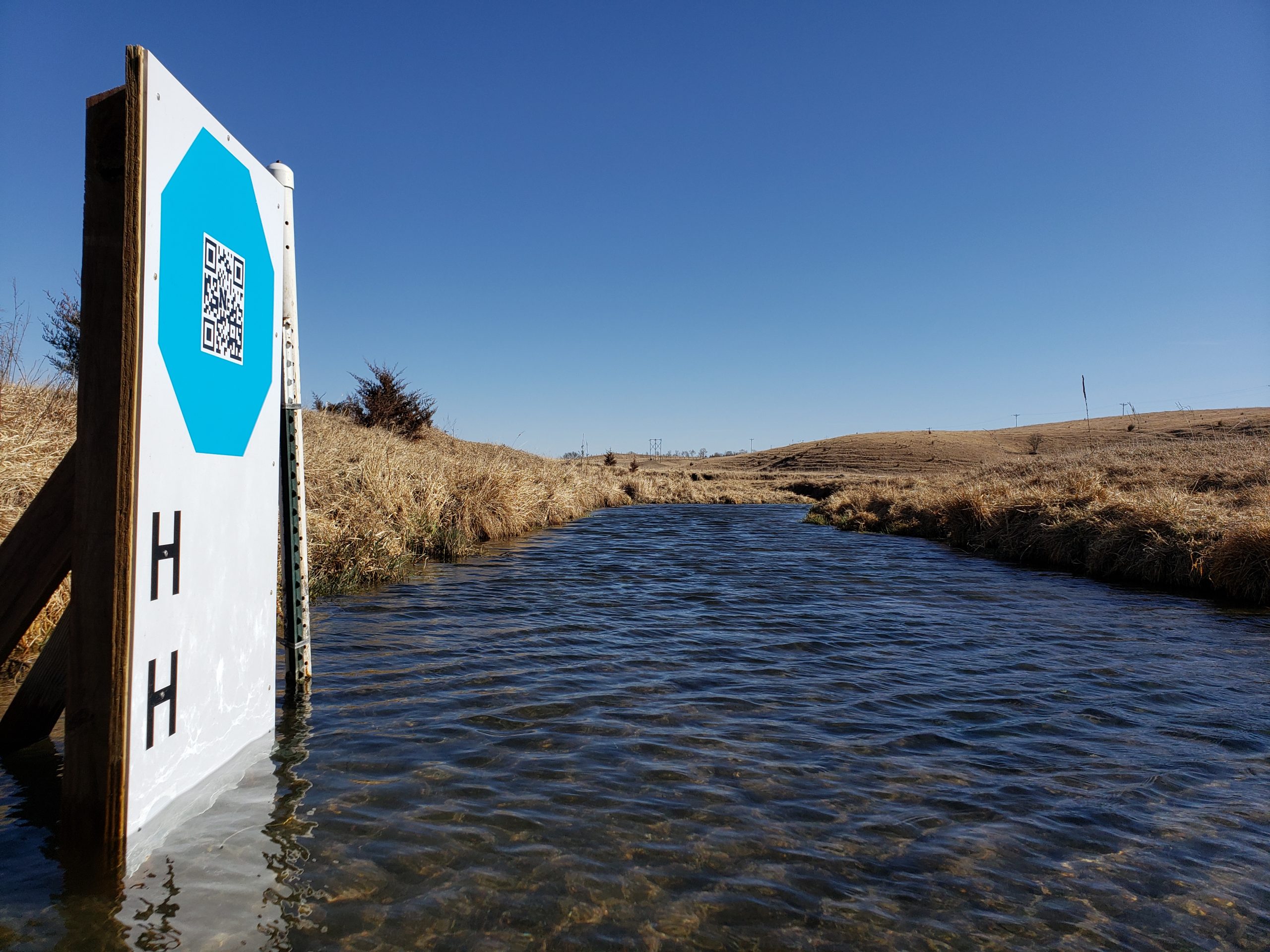
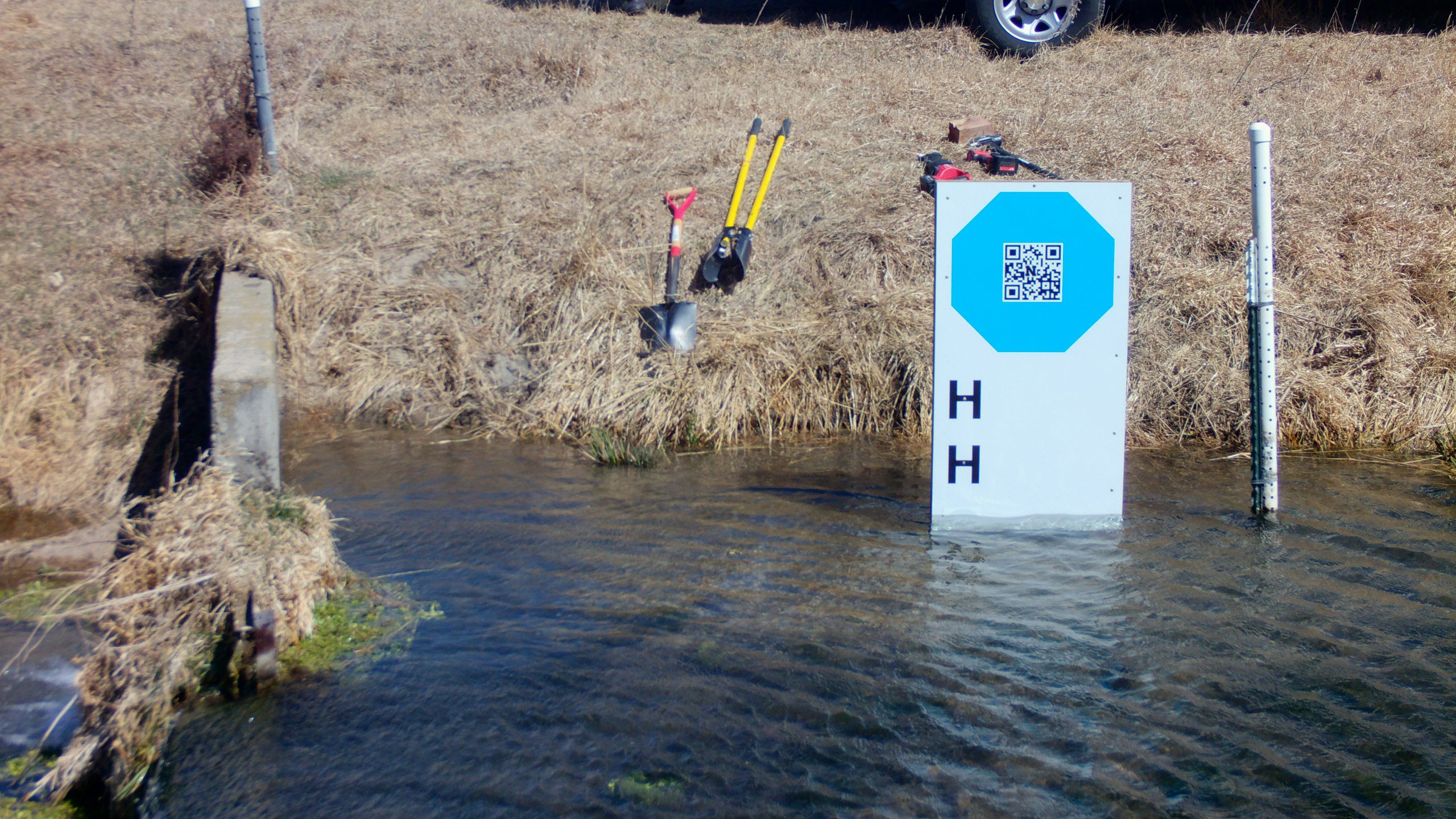
A small photo gallery of a stop-sign target installation in Nebraska:
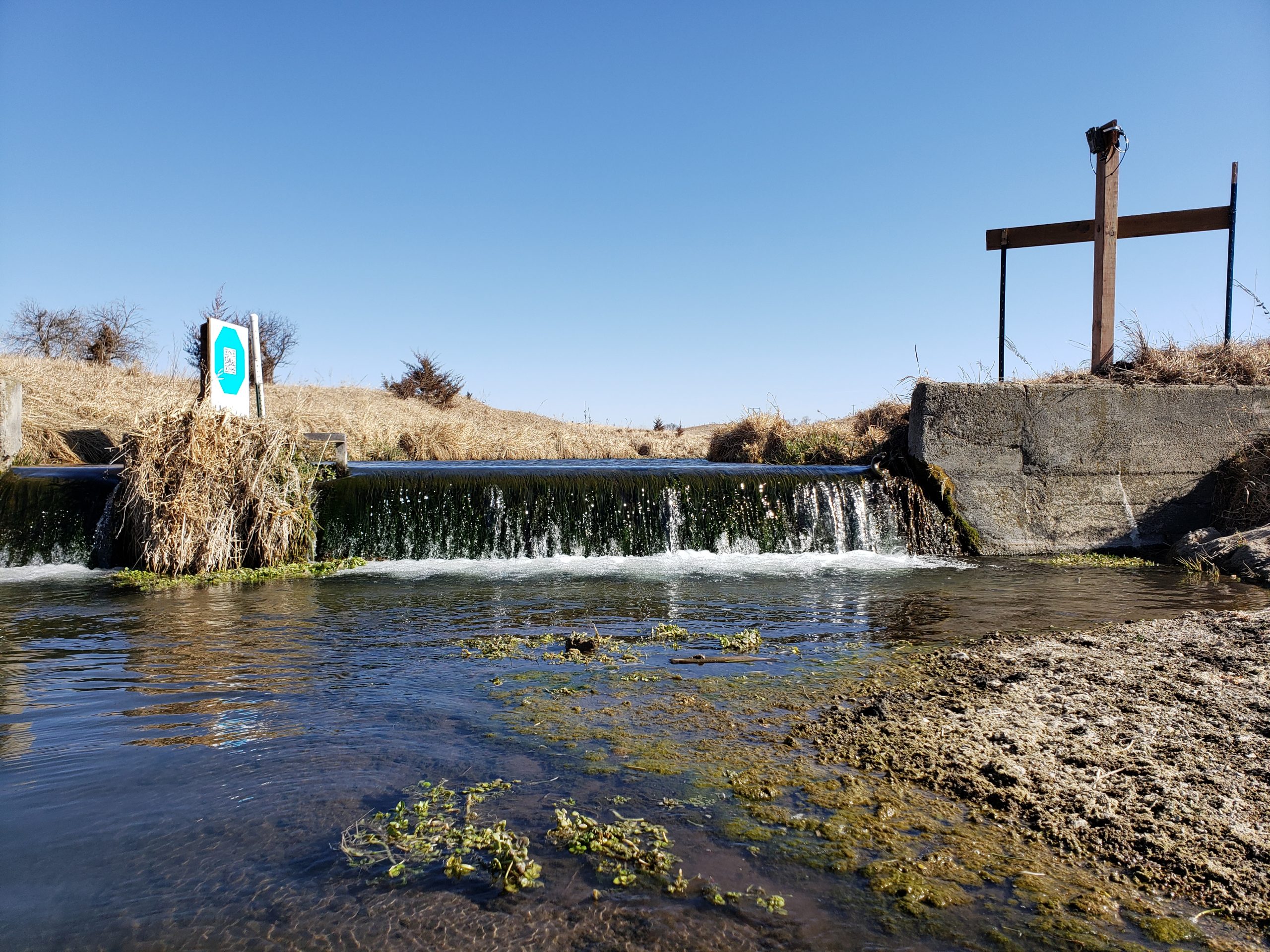
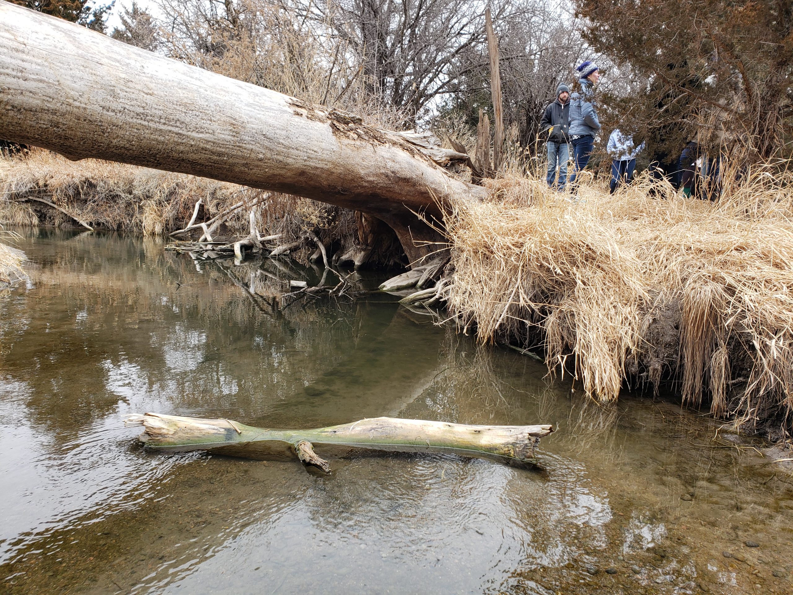
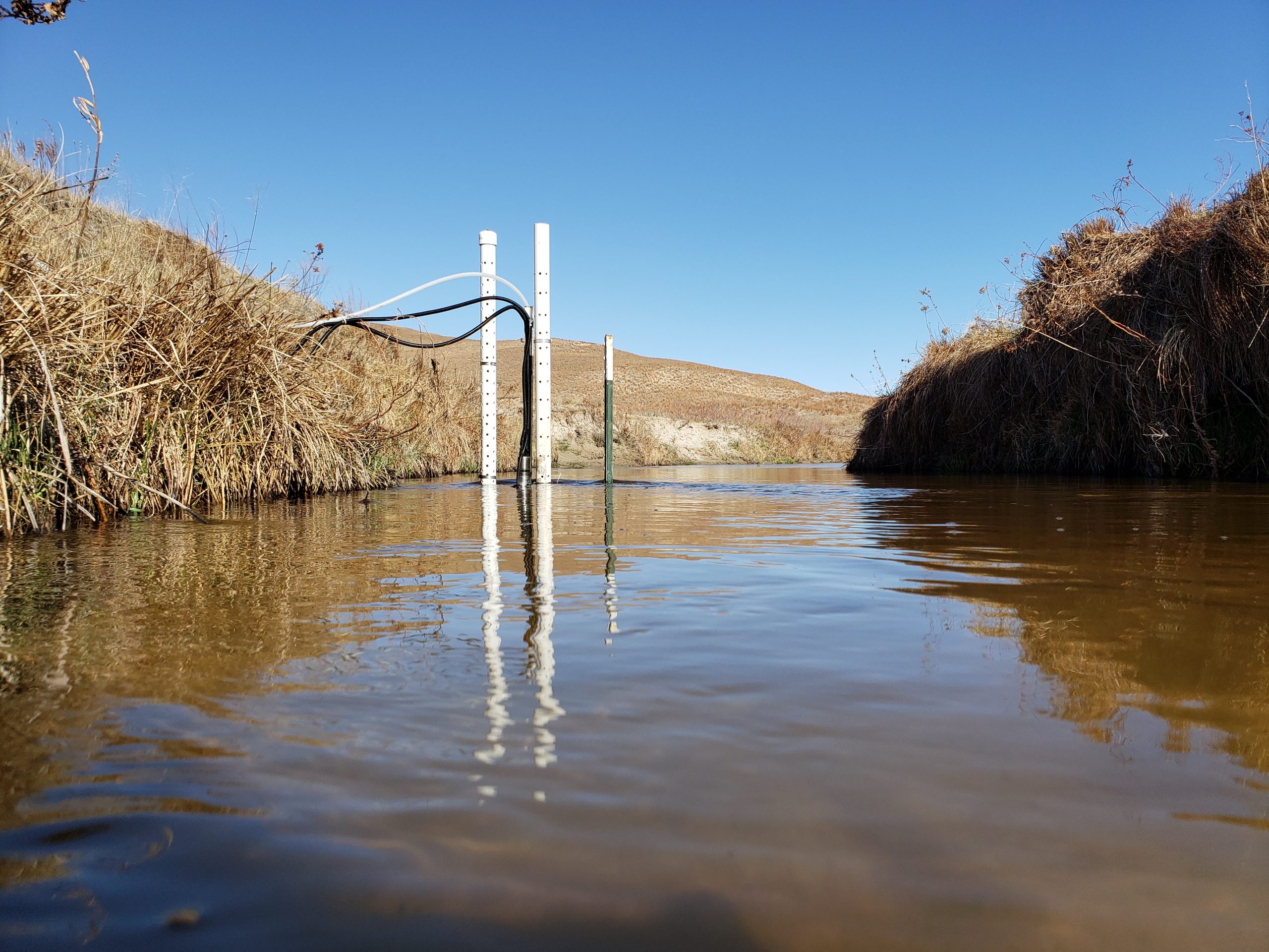
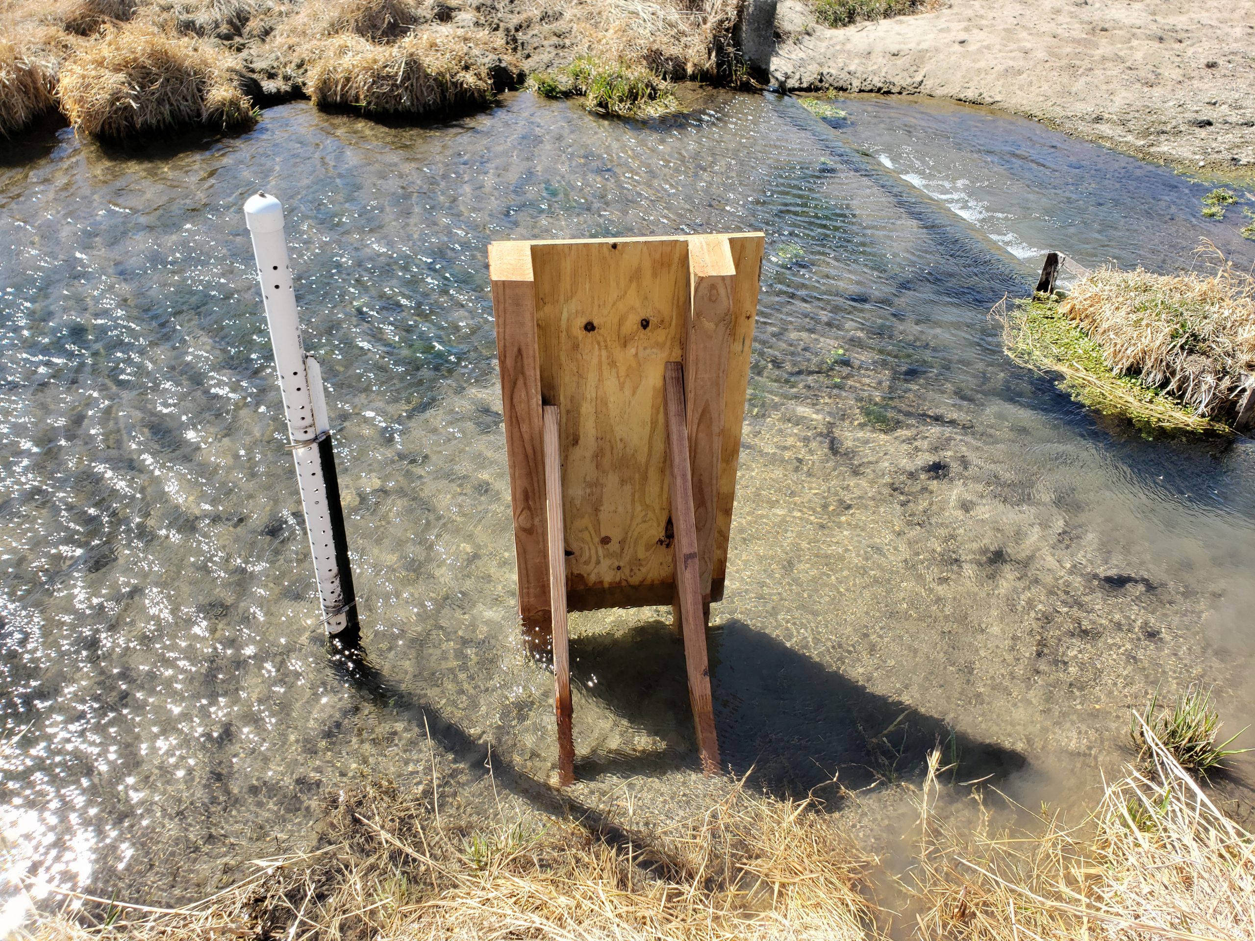
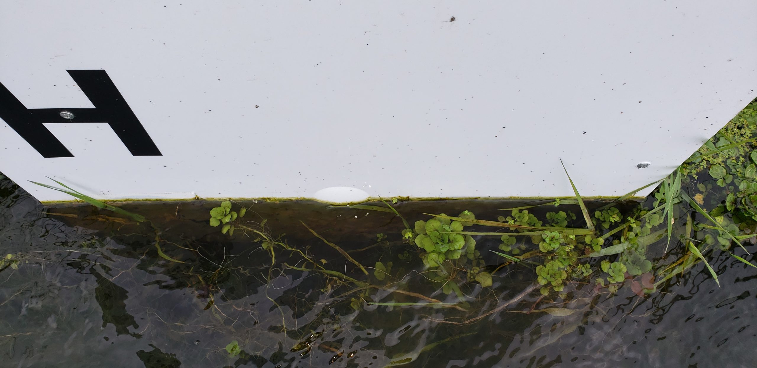
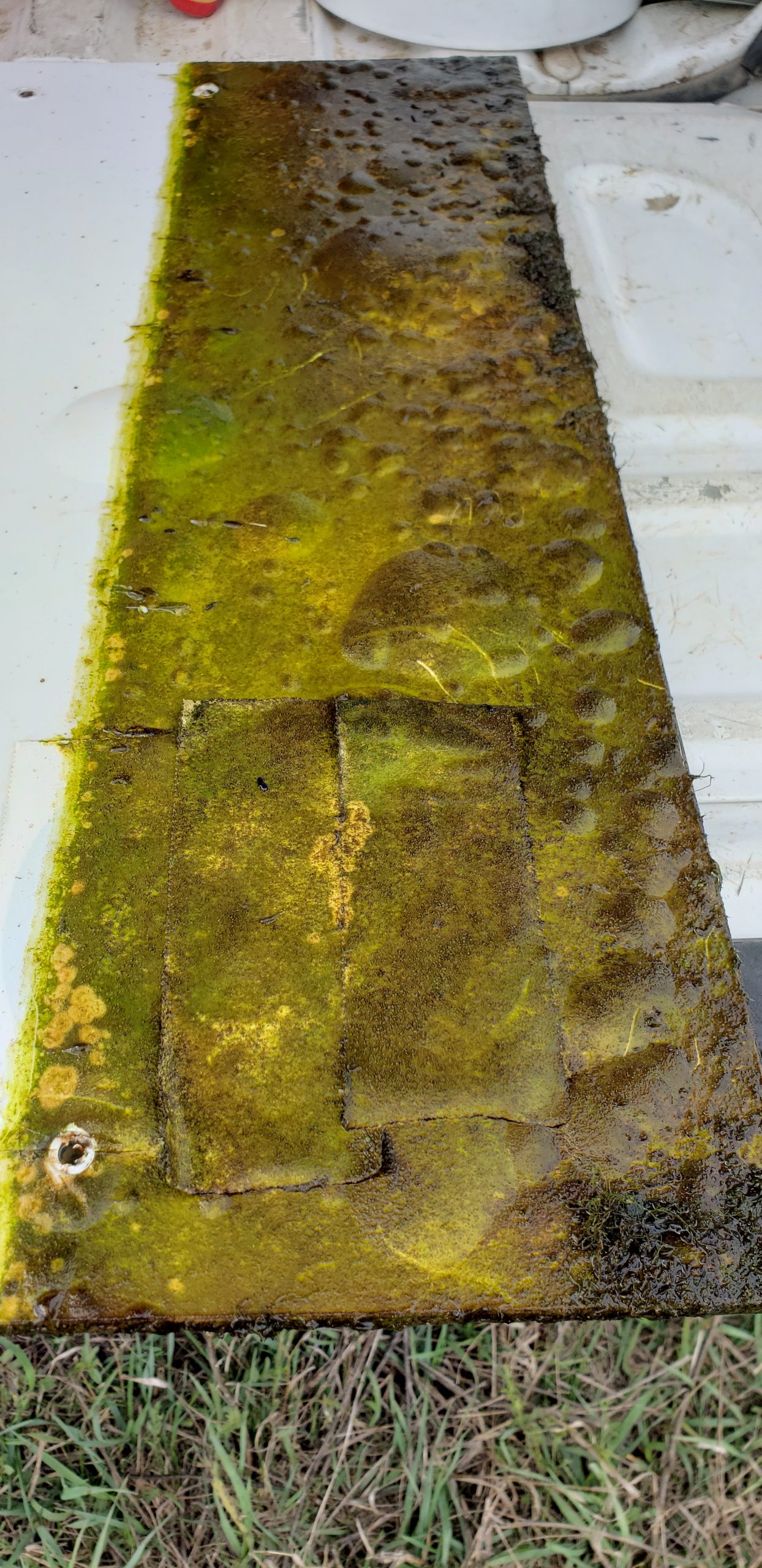
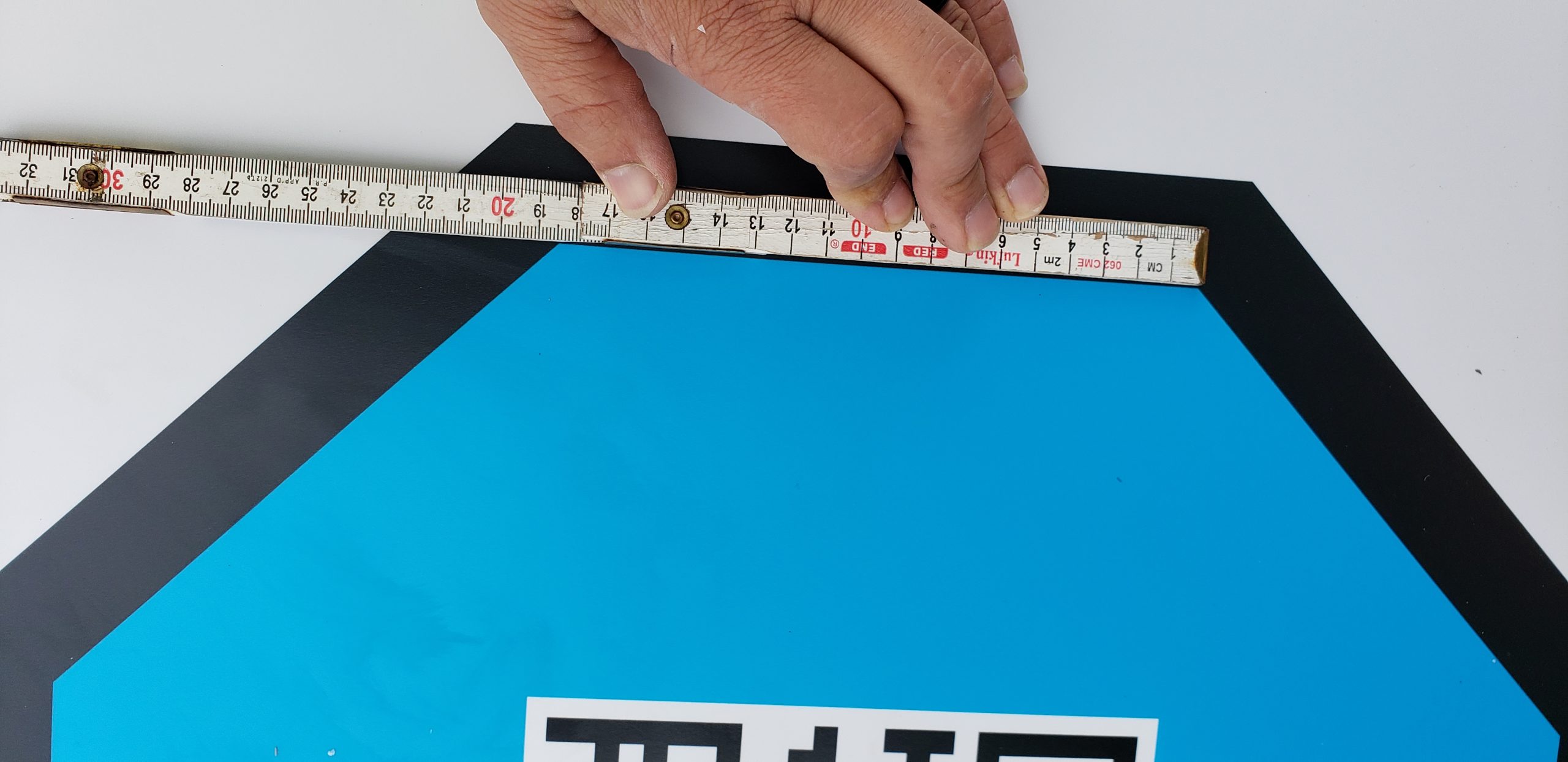
GaugeCam stop-sign target (missing the black octagon outline we’ve since added) in Spring Creek.GaugeCam stop-sign target with additional HOBO water level sensor installed in PVC pipe just upstream..Posts and support construction that hold the target. This must be plumb (target perpendicular to the water surface).GaugeCam camera and background at Spring Creek.Biofouling issues can appear in 7-10 days in this nutrient-rich stream.Biofouling after a month without maintenance. There is also some bubbling of the laminated surface. We are working on these issues, but the target does require maintenance.The stop-sign calibration concept is predicated on the idea that the octagon facets are the same length. This is the key field measurement needed for calibration purposes.
Some practical considerations and details:
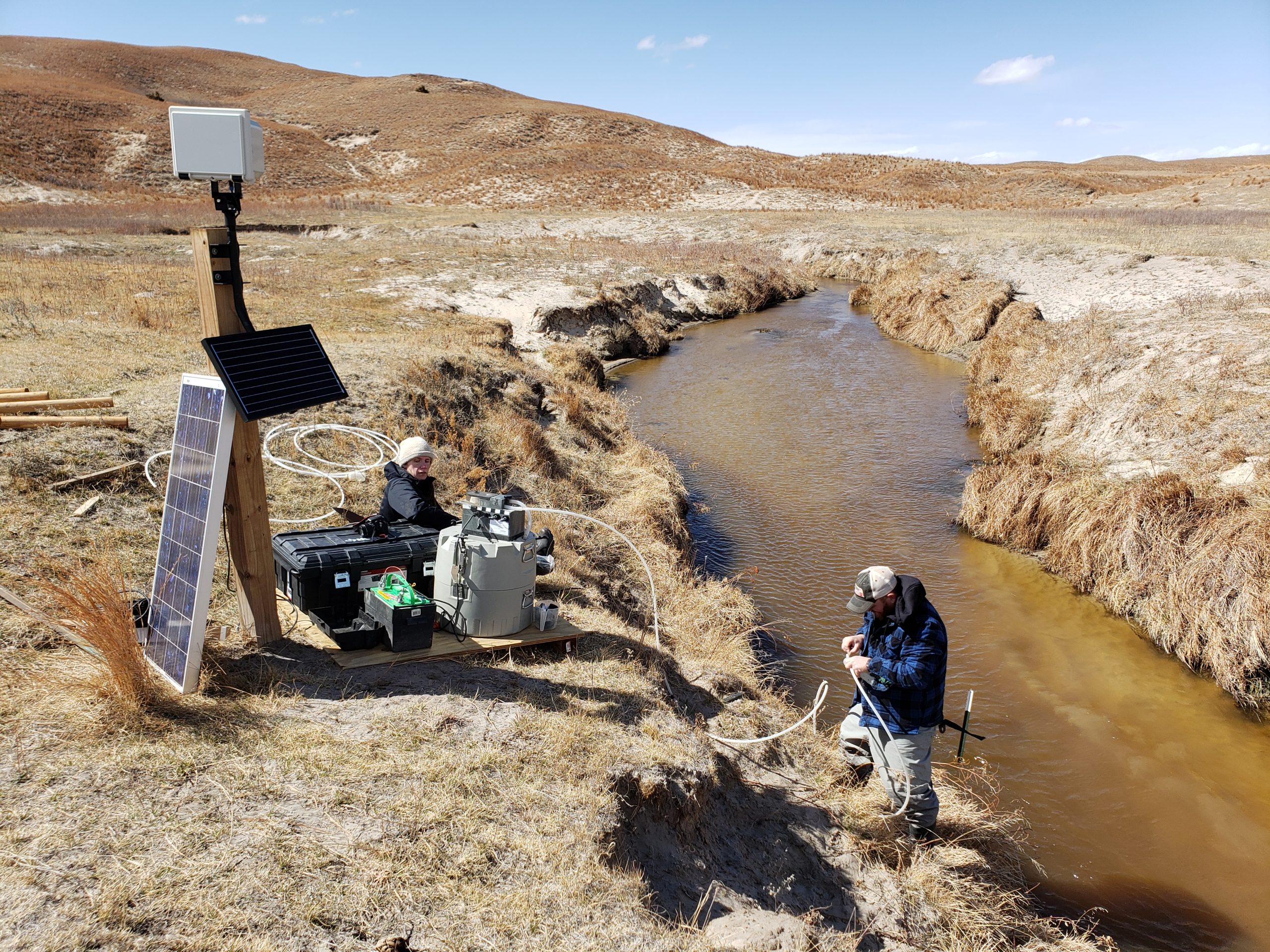
The first question that needs to be answered is the level of reliability and accuracy that is required for your application. If this is an easily-accessed (for maintenance) “demo” site, then this system is perfect for facilitating science communication, etc. If it’s a remote site, with only occasional access for maintenance and data collection, we strongly recommend putting in a cheap transducer alongside the GaugeCam system (e.g., HOBO, $300).
Accuracy depends on (1) how many real-world mm or cm are represented by each pixel in the image, and (2) the quality of installation and maintenance of the background target. The following are issues to consider for field application:
In controlled lab experiments, we can achieve high accuracy (+/- 3 mm, about the size of a meniscus; see Gilmore et al. 2013).
In a carefully maintained tidal marsh installation, accuracy was less, but still quite good (see Birgand et al. 2022).
You will encounter foggy mornings, spider webs on lens, and other similar environmental issues when using cameras. Expect data gaps of minutes to hours due to these issues.
While biofouling is a universal problem for many reasons for many applications and industries, we are actively working to mitigate biofouling affects in our application. In the nutrient-rich agricultural streams where we work, biofouling accumulates within 7-10 days, which requires regular cleaning.
The background must be plumb (perpendicular to the water surface).
The original bow-tie target (template here, nominally 3’ x 4’) was used in the studies above. The new stop-sign target (template here, nominally 2’ x 4’) is experimental, but is smaller and still seems to give pretty good results. The bow-tie requires a survey of the real-world location of bowtie intersections. The stop-sign target requires only the facet length measurement (assumed to be the same for all 8 facets on the printed target) and reference measurement from the bottom left corner.
In terms of installation, here is a parts list from my recent installations in sandy to slightly gravelly streambeds:
Target
Target background, matte print laminated on plexiglass*
Two treated 4×4 posts, 8’ long [NOTE: before digging post holes you should have utilities located; contact your local utilities for this (usually free) service!]
Short (1” or 1 ¼”) pan-head screws (for attaching the plexiglass to the plywood)
Long (3”) outdoor decking screws
Thin wood wedges or spacers (for adjusting background so it is plumb – you might be able to cut these in the field)
Camera
We suggest Reconyx cameras due to their quality, though nearly any game camera will do
Suggest RAM mount products to minimize any camera movement (example 1, example 2)
Suggest adding a lock on camera for security
Suggest treated 4×6 post for mounting the camera; 4×4 post as very minimum.
Camera can be mounted on a large tree or similar, but this will usually create a good bit of movement of the camera. Small amounts of movement can be handled by the software, but minimal movement is better.
*We are looking for a better alternative that does not require as much cleaning and/or is more resistant to biofouling. The matte finish seems like a good attachment surface for biofouling. If you find a local sign shop for printing, I can send you the contact info for my sign shop so they can talk.
**I have used these in the sandy streams, where I cannot dig holes more than ~1 ft into the streambed (the sand collapses in), so adding these spikes on the bottom helps solidify the installation.
***You can print the background on very thick plexiglass and skip the plywood, but I found this to be expensive. So I printed on ¼” plexiglass and mounted on plywood backing.